Lockout Relay Wiring Diagram Hvac Unit
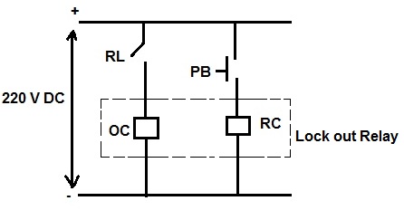
The Lockout Relay Circuit Youtube
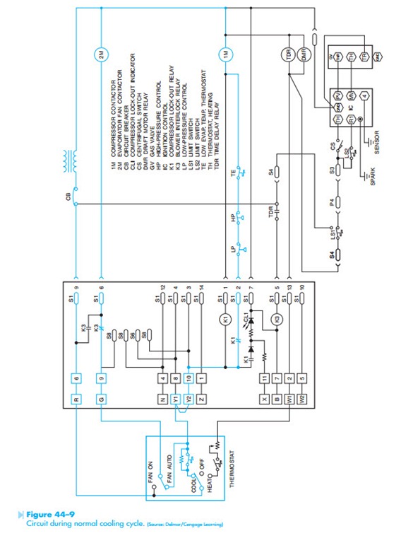
Troubleshooting Using Control Schematics Circuit Operation And
What Is A Lock Out Relay Master Trip Relay Electrical Concepts

The Lockout Relay Circuit
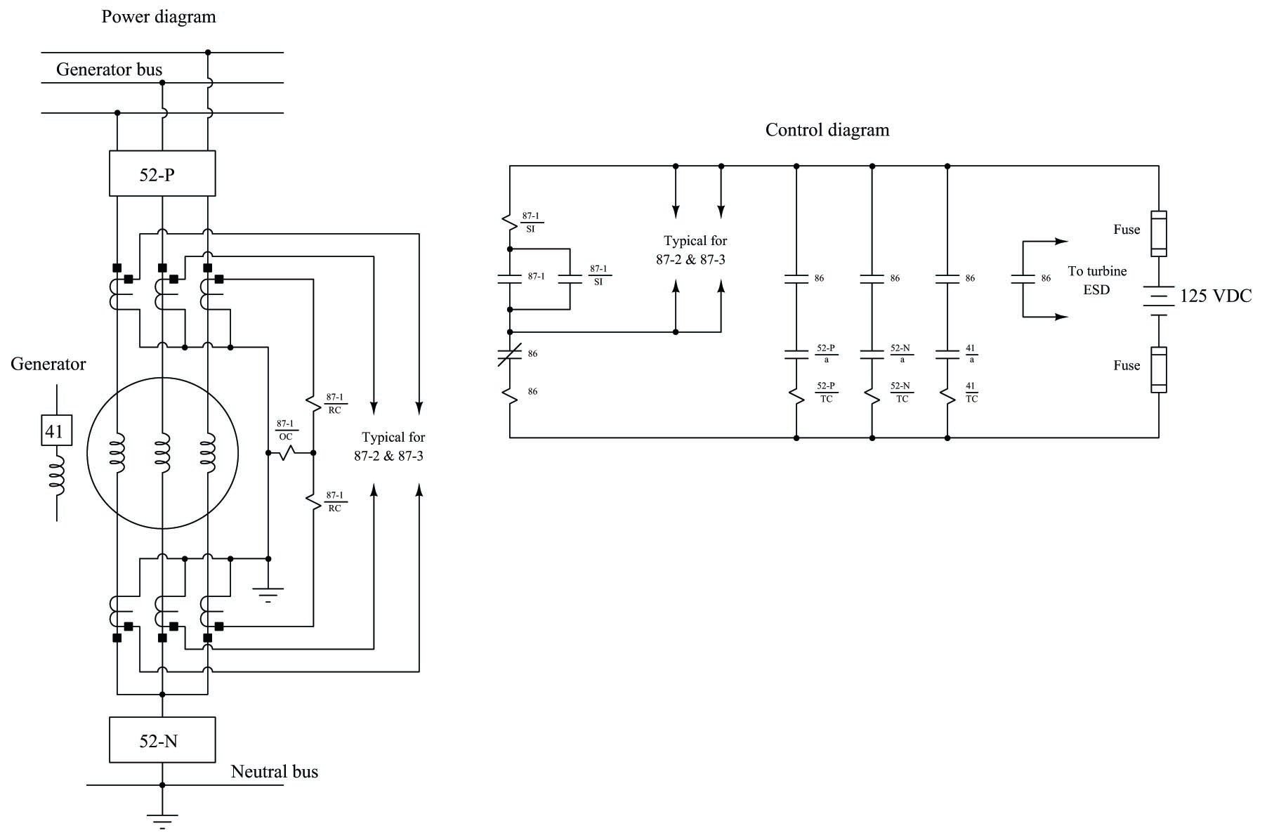
Auxiliary And Lockout 86 Relays Electric Power Measurement And

Dc Relay Wiring Diagram For Fog Lights Best Wiring Diagram
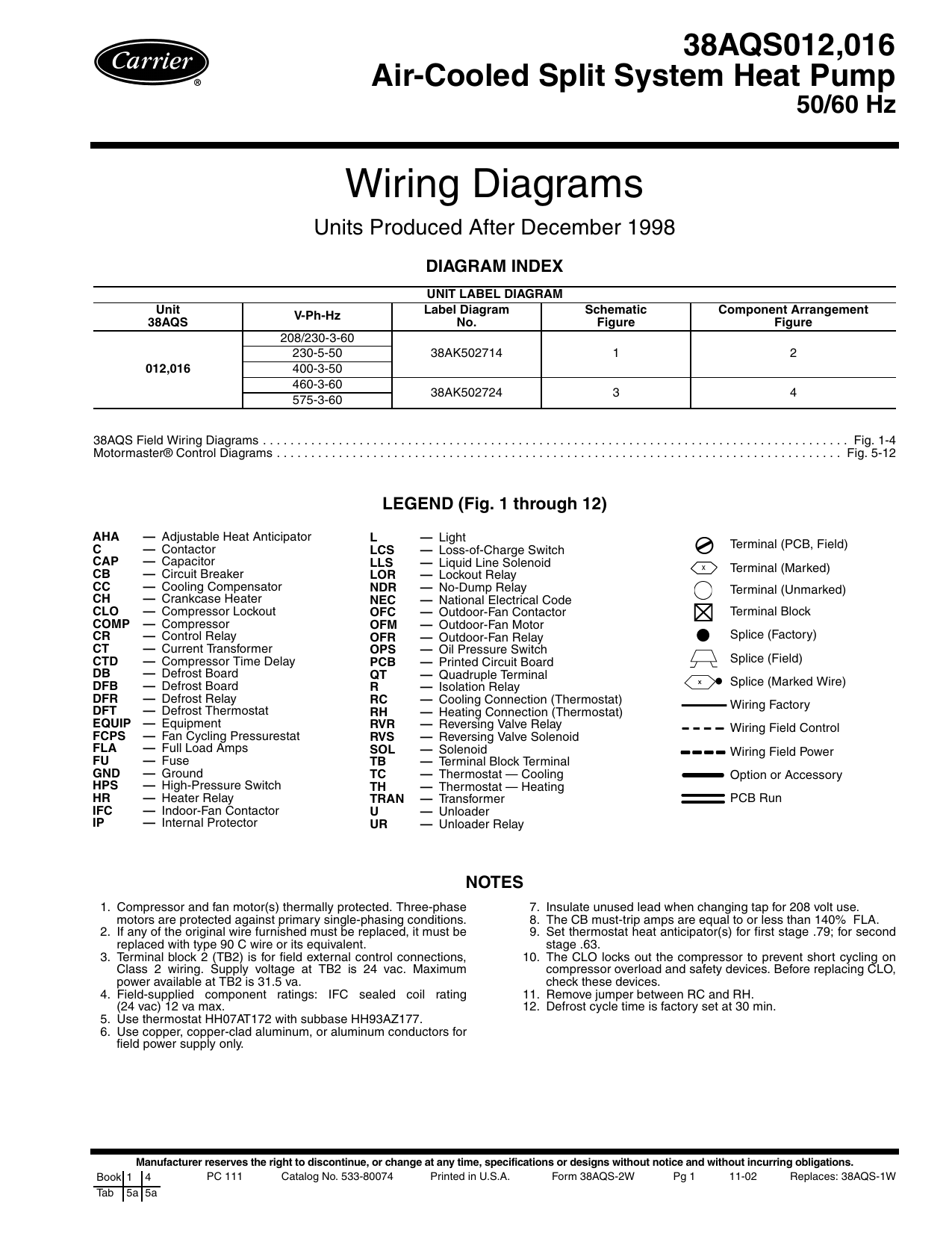
Use copper conductors only.
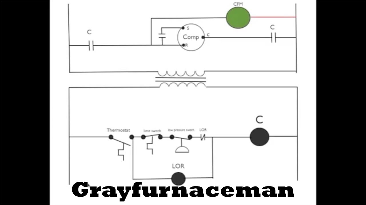
Lockout relay wiring diagram hvac unit. All units except 460 v 3 ph 60 hz use motor master control carrier part no. It normally shows only what the terminal board connections are and very rarely will it include any internal wiring of the unit. It reveals the parts of the circuit as streamlined shapes and the power as well as signal connections between the devices. This one demonstrates how the lockout relay circuit works.
How to wire an air conditioner for control 5 wires the diagram below includes the typical control wiring for a conventional central air conditioning system furthermore it includes a thermostat a condenser and an air handler with a heat source. Not suitable for use on systems exceeding 150 volts to. Install snap acting hvac relays from grainger in any position for remote control of air conditioning heating and ventilation systems. 12 power wiring must comply with all local and national requirements.
A wiring diagram is a simplified standard photographic depiction of an electrical circuit. Moreover the heat source for a basic ac system can include heat strips for electric heat or even a hot water coil inside the. Wiring diagrams units produced after december 1998 diagram index. Lor lockout relay.
1 and 2 1. This is a tool that is used primarily by the installing contractor. The third and last type of diagram is the installation diagram. Variety of hvac fan relay wiring diagram.
Control fans blowers motors up to 1 1 2hp tools and other electrical devices within ratings. Figure 3 is a typical installation diagram for a residential cooling system. Wiring diagrams index units produced after 03 31 03. Field modifications or additions must be in compliance with all applicable codes.
44 electroswitch 180 king avenue weymouth ma 02188 tel.
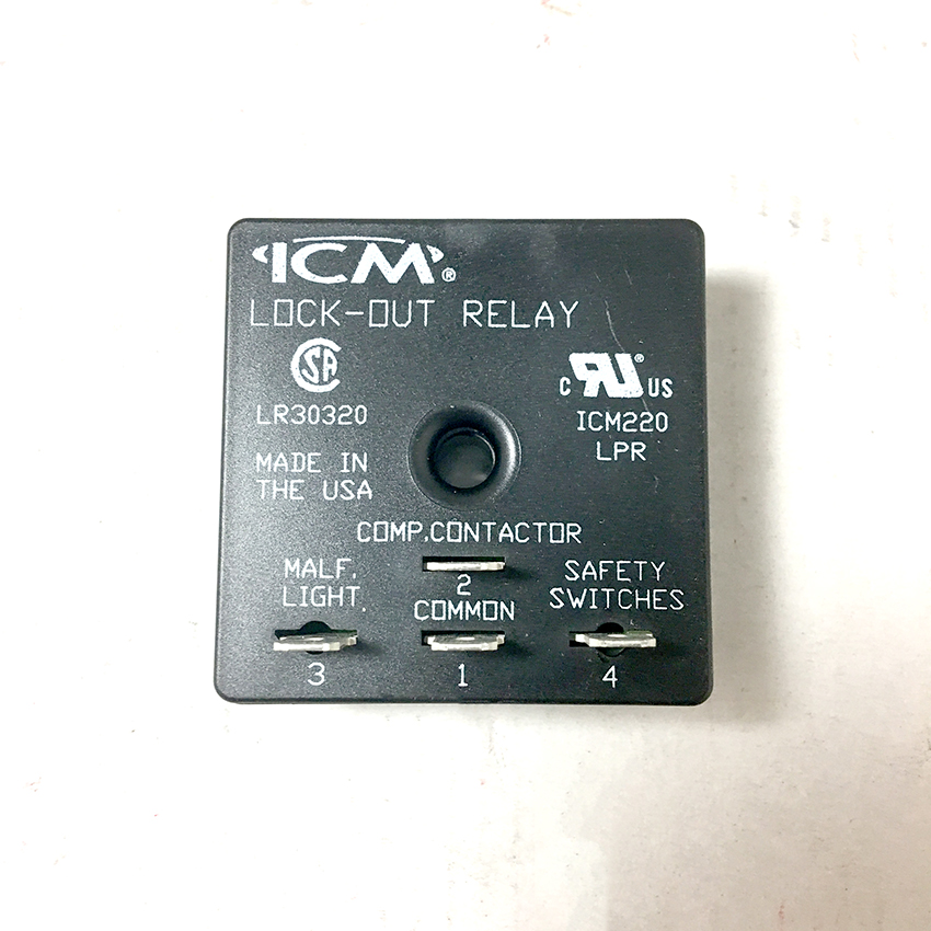
Icm Lockout Relay Icm220b Shortys Hvac Supplies
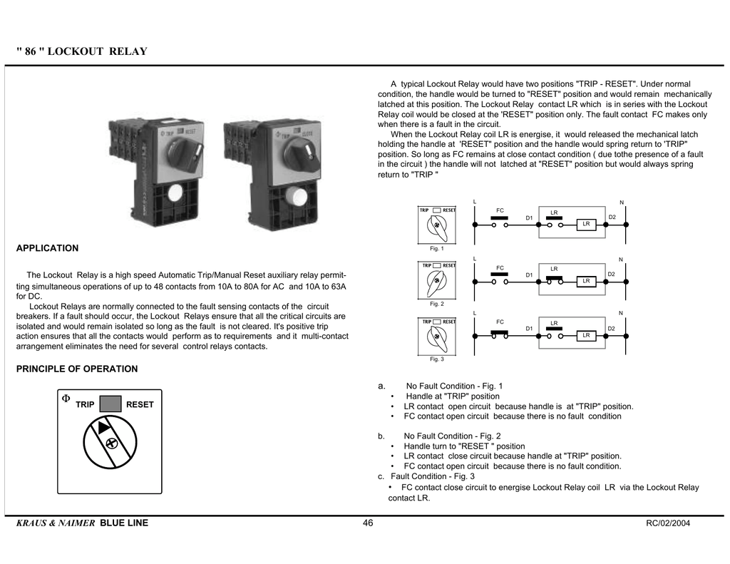
86 Lockout Relay

Pin On Relay Protection
Wiring Diagrams Manualzz

Wiring Diagram For A Simple Fire Alarm System Best Of Amazing

Unique Schematic Symbol Switch Diagram Wiringdiagram

4 Essential Implementations Of Protective Relays In Power Systems

Gas Club Car Wiring Diagram 3 Gas Golf Carts Golf Carts Golf

Electrical Symbols Electrical Symbols Electricity Electrical

2003 Dodge Ram 2500 Ecm Wiring Diagram Wiring Diagram By Wiring

The Principles Of Differential Protection You Must Understand

The Principles Of Differential Protection You Must Understand

Eecs 463 With Images Computer Science Electrical Engineering
