Mag Ic Flow Meter Wiring Diagram
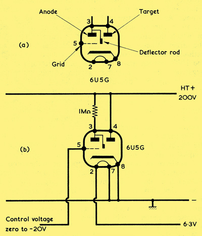
The Magic Eye Tuning Indicator

Repair Guides Wiring Diagrams Wiring Diagrams Wiring Diagrams

Pin On Instrumentation Tools
Https Www Instrumart Com Assets Flocat Mfe Installation Manual Pdf

Electromagnetic Flow Meters Design Considerations Analog Devices

Common P Id Symbols Used In Developing Instrumentation Diagrams
Two page wiring diagram below download here.
Mag ic flow meter wiring diagram. Includes single phase 2 phase supply 3 phase supply multiple installations distributed generation alternative energy and typical equipment dimensions. The meter must be returned to the factory for electrode replacement. As illustrated in figures 2 3 and 2 4 avoid downward flows. Pump unhook the pump disconnect the water circuit connections a and from the supports.
Vertical installation allows upward process fluid flow and is generally preferred. The mag meter isolating liner is not intended to be used as gasket material. See video instructions here. Flow meter lift the fl ow meter out of the casing assembly and remove the electrical and water circuit connections.
For teflon lined meters replacement of the electrodes must not be attempted in the field. The flow meter consists of metal and plastic parts all of which must be in compliance with local rules and. Copper wire wafer type sensors common ground plant bonding 2 grounding 4mm 10 awg 2 copper wire common ground plant bonding 2 flow supplied bonding cable grounding ring upstream flange preferably common ground plant bonding 4mm 10 awg copper wire 2 1 full bore sensors caution. 4 20 internal and external wiring guides for 4 20 as well as 1 5 vdc across a 250 ohm resistor the 0 5 vdc hookup and the pulse counter connections.
6 7 exercise extreme care when withdrawing the electrode from its seat so that little or no tension is exerted on the connecting electrode wire. Reference manual 00809 0100 4444 rev ag october 2018 rosemount 8732em transmitter with hart protocol reference manual. For applications that require high working pressures or substances that may be hazardous to the. Do not rely on the flange bolts or studs for.
I o wiring and specifications 3 6 i o wiring and specifications in the previous section on sourcing and sinking concepts we explained that dc i o circuits sometimes will only allow current to flow one way. Meter wiring diagrams for low voltage meter stations for in whangarei and kaipara. When installing the gaskets make sure they are properly centered to avoid flow restriction or turbulence. Orientation of the electrode plane is unimportant in vertical installations.
Standard gaskets not provided should be installed to ensure a proper hydraulic seal. With the wiring diagram. These diagrams give the details of the circuitry behind the connections you need to use the mass flow meter. Electrical connections b loosen the safety valve c and slide the pump off the brackets d.
Install the meter with enough room for future access for maintenance purposes. Upward flow keeps the cross sectional area full regardless of flow rate. Minuto 07 disassembly 7 9.

Process Instrumentation Flow Measurement Magnetic Flow
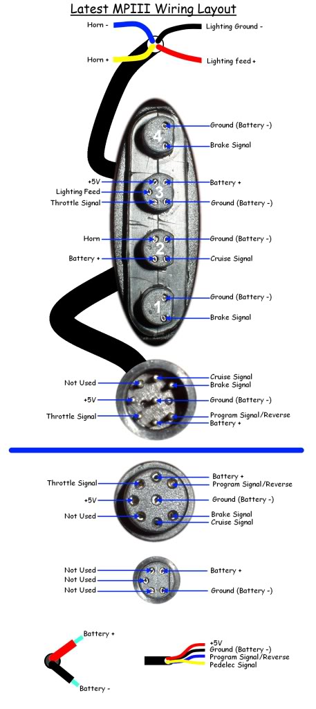
Magic Pie Iii Wiring Problems

Pin On Transformatory

Photo Switch Circuit Light Sensor Circuit Circuit Ldr Circuit

Fuel Tank Pressure Sensor Problems And Check Engine Lights
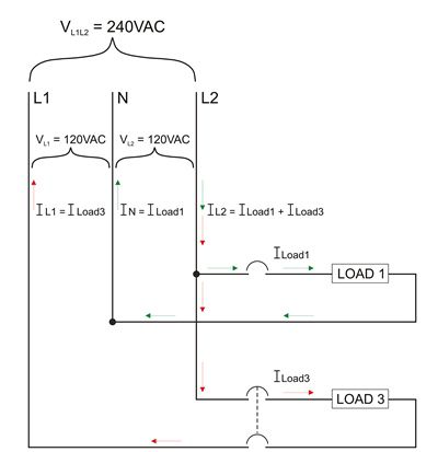
Current Flow In 120 240 Volt Ac Systems Blue Sea Systems

Panic Alarm Circuit Diagram Circuit Diagram Circuit
Temperature Measurement Using Lm35 And Avr Microcontroller
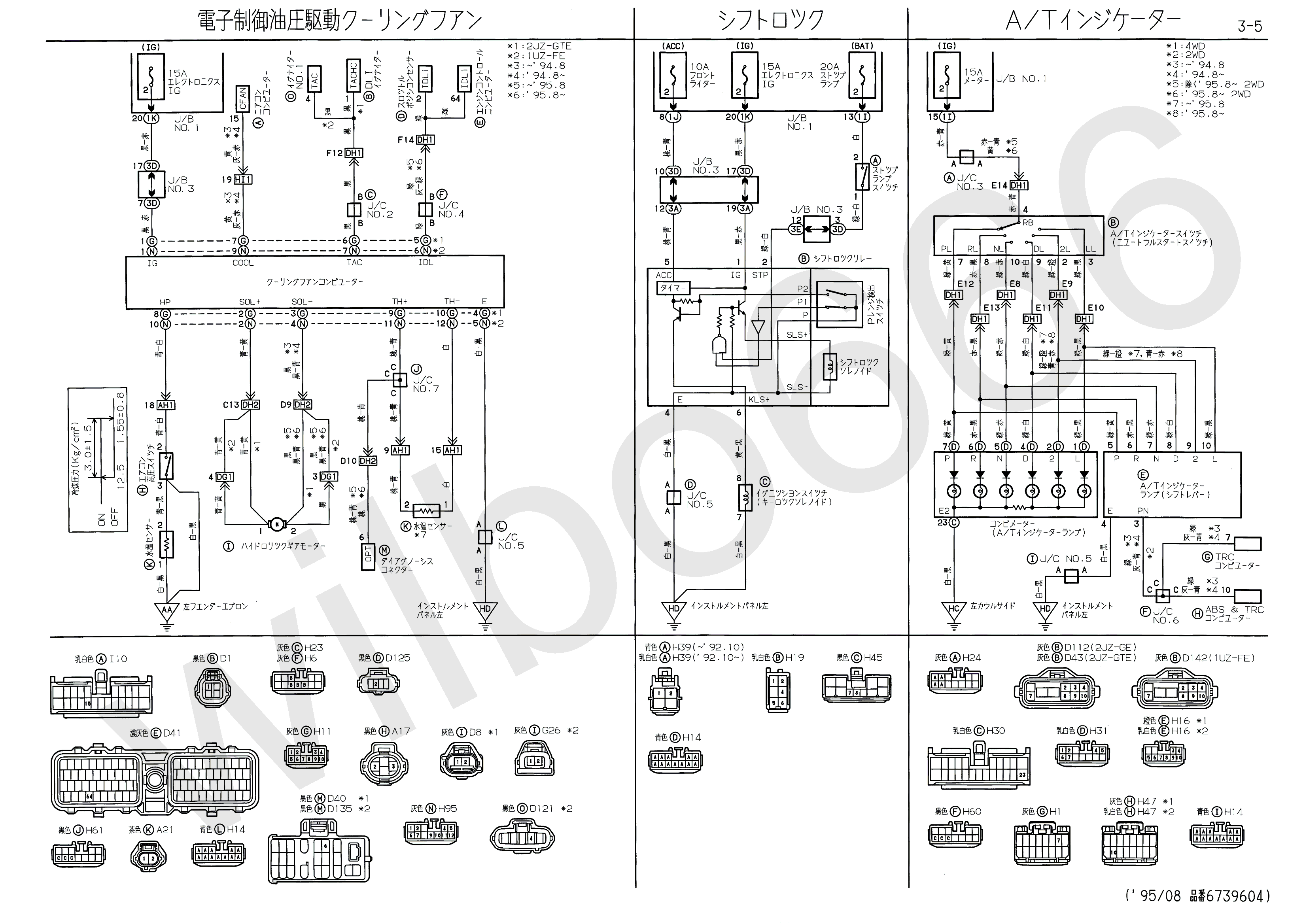
Wilbo666 2jz Gte Jzs147 Aristo Engine Wiring

Window Ac Wiring Diagram Online Ac Wiring Thermostat Wiring

Transmission Wiring Can I Get A Chevy 4l60e Diagram Please Best Of

Electromagnetic Flow Meters Achieve High Accuracy In Industrial

Pin Su Garduino