Mallory Alternator Wiring Diagram

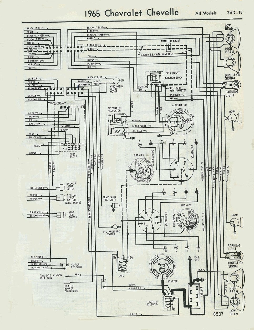
Mallory ignition coil wiring diagram wiring diagram is a simplified agreeable pictorial representation of an electrical circuit.
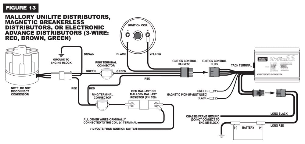
Mallory alternator wiring diagram. Installation instructions 3 mallory www mallory ignition com 915 857 5200 fa 915 857 3344 ballast resistor. Tachometers the yellow wire on the hyfire 6a ignition control provides a. Recommend mallory s promaster coil p n 29440 or 30440. How do i wire my mallory distributor.
Whether you have the mallory unalite or dual point with or without our power amplifier you will find below a wiring diagram to suit and also the original instructions that come with the mallory distributors. The purpose of an ignition ballast resistor between the ignition switch 12v and the ignition coil positive terminal is to restrict current flow. As a matter of fact a bad diode trio in a conventional alternator can do the same damage. Ford alternator wiring diagram this is the diagram of every components in the alternator.
It shows the components of the circuit as streamlined forms as well as the power and also signal links between the tools. Routing wires the hyfire wires should be routed away from direct heat sources such as exhaust manifolds and headers and any sharp edges. It is a diagram for the alternator in a ford focus see also ford focus repair manual ford escort ford f 100 ford taurus ford mustang ford model t ford gt40 ford thunderbird ford shelby cobra and other ford cars that use the similar alternator. Collection of mallory ignition wiring diagram.
A wiring diagram is a simplified standard pictorial depiction of an electrical circuit. Mallory s promaster coil p n 29625 can also be used as well as most stock coils or aftermarket coils designed as stock replacements. If your vehicle has a ballast resistor in line with the coil wiring it is recommended to bypass it. Do not use mallory s promaster coil p n 28880.
It shows the components of the circuit as simplified shapes and the capacity and signal connections amongst the devices. And connect the red wire to the output side of the alternator 10 32 stud take the long wire and connect to the side of the coil.


