Mallory Distributor To Msd Wiring Diagram Free Picture

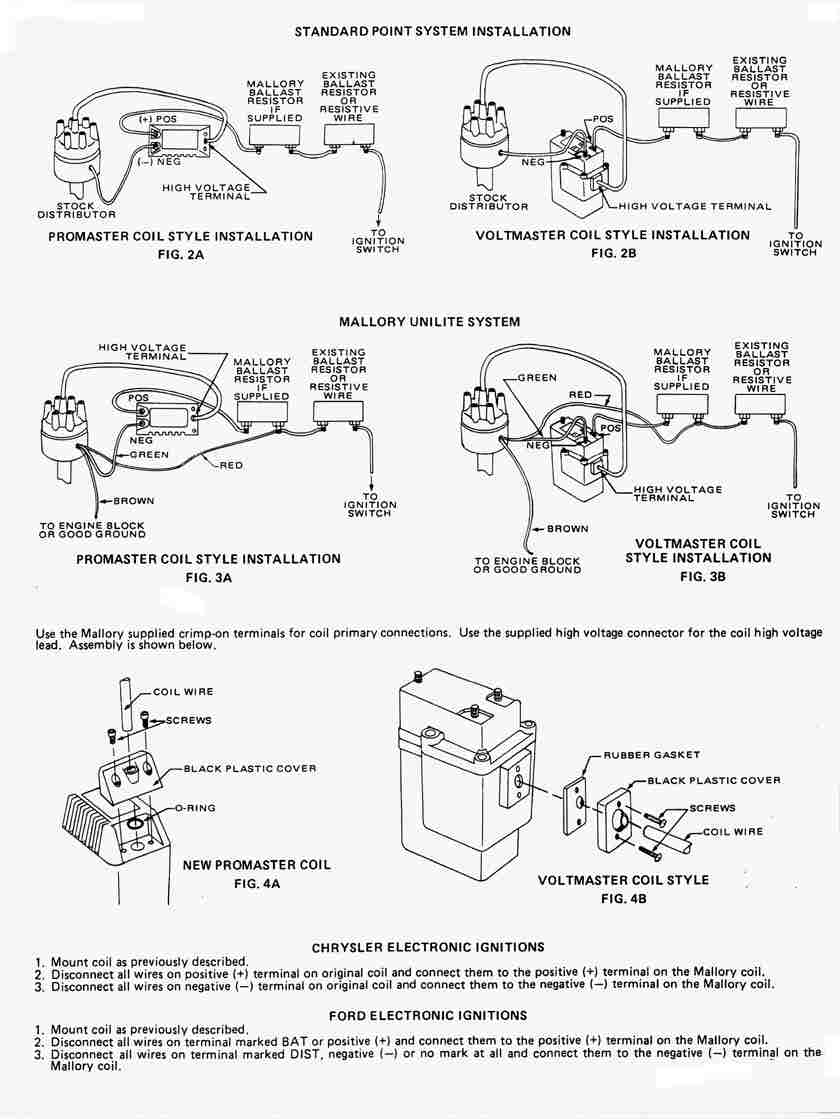
According to the unilite installation manual on mallory s web site the wiring diagram shows connecting the distributor directly to the 12v side of the ballast resistor and the coil is the only thing on the low side of the resistor.
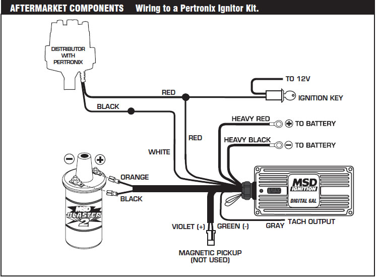
Mallory distributor to msd wiring diagram free picture. Mallory comp ss distributor wiring diagram wiring diagram is a simplified customary pictorial representation of an electrical circuit it shows the components of the circuit as simplified shapes and the power and signal friends in the middle of the devices. It shows the components of the circuit as streamlined forms as well as the power and also signal links between the tools. 10 start the three wires of the mallory unilite module through the hole in the nose 14 route the wires from the unilite module to the ignition coil carefully 16 follow a factory shop manual to set the timing for your particular engine wiring diagram for mallory distributer don t worry if your coil doesn t look like this american one or. 96 99 orange purple mallory harness p n 29040 red black msd orange black violet black.
A wiring diagram is a simplified standard pictorial depiction of an electrical circuit. The purpose of an ignition ballast resistor between the ignition switch 12v and the ignition coil positive terminal is to restrict current flow through the ignition coil. So if you would like get all these amazing shots about msd distributor wiring diagram. Failure to use an ignition ballast resistor will.
Figure 12 wiring to a mallory 3 wire distributor. Collection of mallory ignition wiring diagram. Were you actually having problems burning up the unilite modules or are you just trying to play it safe by wiring it this way. The following wiring diagrams show common installations.
Here is a picture gallery about mallory ignition wiring diagram complete with the description of the image please find the image you need. 81 and 84 orange purple mallory comp 9000 series nos.


