N52 Crankshaft Sensor Wiring Diagram

N52 Crankshaft Sensor Wiring Diagram H1 Wiring Diagram
E9f N52 Crankshaft Sensor Wiring Diagram Wiring Resources

Bmw N52 54 Crank Sensor Harness Repair Zero Lag Performance

Pelican Parts Technical Article Bmw X3 N52 Engine Crankshaft

N52 Crankshaft Sensor Wiring Diagram H1 Wiring Diagram

Pin On Ecm Ecu Repair Test Platform

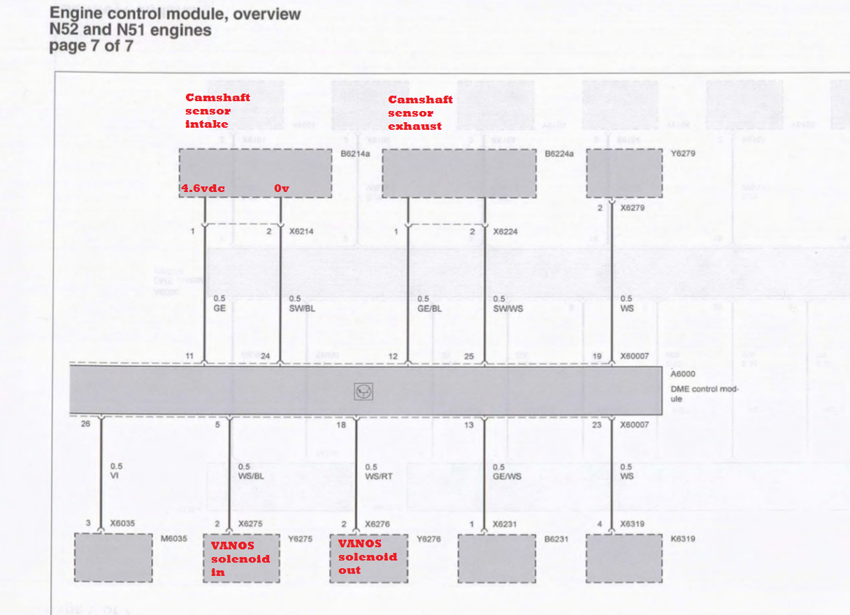
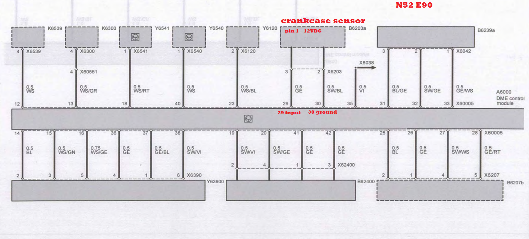
Terminal 1 is the sensor reference voltage.
N52 crankshaft sensor wiring diagram. Ohm wire to ground. Check your model against a current wiring diagram. In this case it is easier to access the dme for testing than it is to access the crankshaft sensor connector. Only shows 2 vanos solenoids and 2 cam sensors in circuit i think there s more on the circuit but i m not 100.
2006 bmw 530i n52 crank no start i pulled codes went to in. The sensor reads a toothed reluctor wheel mounted to the end of the crankshaft. The crankshaft position sensor is located near the starter motor mounted in the engine block. Kinda can see it on vantage.
I used alldata for wiring diagram and incomplete. Cam sensor to measure power grounds and signal. Purple arrow wiring color and dme terminal locations may vary. Green arrow terminal 2 is sensor ground signal wire.
Crankshaft position sensor wiring harness diagram bmw e90 e91 e92 e93 if you need to find the crankshaft position sensor wiring harness and the wire order for the crankshaft position sensor on bmw. Using the signal from the crankshaft sensor the ecm knows which cylinder is ready for fuel intake and then later for ignition. Testing the signal at the dme is the preferred method anyway because it eliminates any faults in the signal wiring from the. Manual peugeot 207 cc pdf.
Yellow arrow terminal 3 is the sensor supply voltage. A quick look at the wiring diagram and component locations gives us some idea of how to test the system.

Pin On Emission Systems Car And Truck Parts
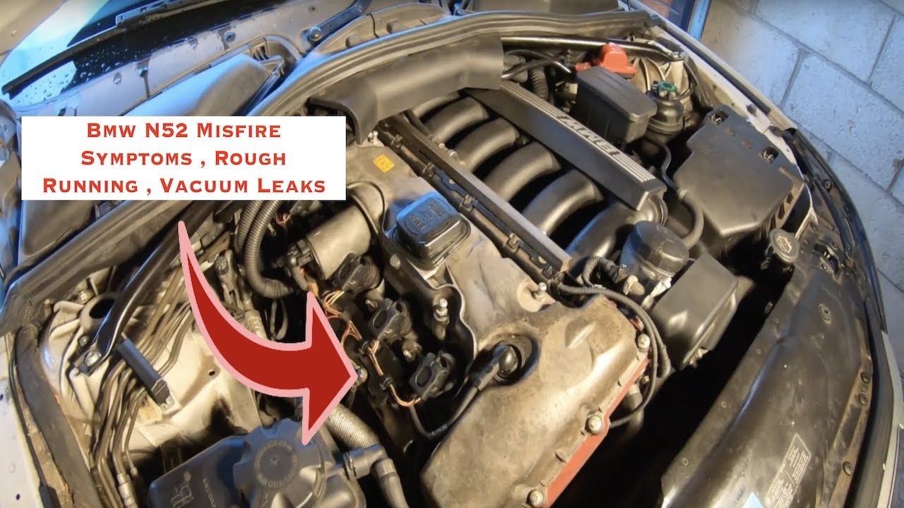
Bmw N52 Common Misfires Rough Idle And Vaccum Leaks Symptoms
System Overview For Engine N52 E60 E61 E63 E64 E65 E66 E70
Bmw E90 E92 N52 How To Replace Valvetronic Motor Gasket Z4 525i

Pin On Haircuts

Pin On Hair
Crankcase Return Pipe Early N52 E90 325i 330i E60 525i 530i
11 31 505 Adjusting Camshaft Timing N52

Pin On Electrical Wiring Diagram

Coloring Pages Mandala Animals Turtle Coloring Pages Mandala
2006 325i E90 Won T Start 3 Camshaft Codes And Thermostat Code
Bae0e03 2008 Volvo S60 Fuse Box Manual Book And Wiring Schematic

Bmw Front Main Crankshaft Oil Seal Removal And Install N40 N42
