Tekonsha Voyager Wiring Diagram 01 96

2000 Gmc Sierra Headlight Wiring Diagram Wiring Diagram Database

Vn800 Wiring Diagram Kawasaki Vulcan Forum

8d2435e 1998 Plymouth Grand Voyager Fuse Diagram Wiring Library

Town And Country Engine Wiring Diagram H1 Wiring Diagram

Plymouth 1936 Standard P1 Deluve P2 Plymouth 1937 Standard P3
Wiring Diagram For 1995 Plymouth Voyager Wiring Diagram Images
Assortment of tekonsha voyager wiring diagram.
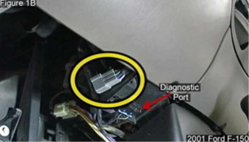
Tekonsha voyager wiring diagram 01 96. Following the wiring diagram included with the controller run the blue wire through the firewall and to the rear of the vehicle where it will connect to the trailer connector. All other servicemarks and trademarks are the property of their respective owner. Tekonsha the tekonsha logo and tekonsha graphics are the servicemarks trademarks or registered trademarks owned by horizon global corporation. Click on the image to enlarge and then save it.
Tekonsha brake controller wiring diagram wiring diagram for trailer brake controller best tekonsha voyager wiring diagram for trailer brake controller 9030. Wiring diagram tekonsha voyager brake controller 39510. Tekonsha voyager wiring diagram tekonsha voyager electric brake controller wiring diagram tekonsha voyager installation instructions tekonsha voyager wiring diagram every electric structure is made up of various distinct components. The voyager incorporates patented braking sensor by tekonsha and is the best value you will find for smooth and secure trailer braking.
A wiring diagram is a streamlined standard pictorial depiction of an electrical circuit. You will want to make sure that you ground the white wire to the negative post on the battery. 6 x 3 8 screws. Warning the brake control must be mount ed from 20 degrees nose down to 70 degrees nose up.
Since draw tite has always strived to provide the right trailer towing activator ii electronic brake control for 1 to 4 axle trailers timed actuated. It is compact size and features like a bicolored led brake monitor to assure a complete connection to trailer brakes and give an indication of relative braking power being applied make the voyager extremely versatile. Otherwise the structure won t function as it should be. Collection of tekonsha brake controller wiring diagram.
Below you will find a link to the installation instructions. I have attached a basic brake controller wiring diagram for you. I have a tekonsha voyager control and need a copy of the wiring diagram for installation. Drawtite activator 2 wiring diagram draw tite activator trailer brake controller 1 to 2 axles time delayed wiring diagram tekonsha voyager brake controller trailer brake.
Thank you in advance for your assistance. See below failure to install brake control within these constraints may cause your control to become inoperable. It shows the parts of the circuit as simplified shapes and the power and signal links in between the gadgets. Yes we can help.

Under Hood Fuse Box Diagram Chevrolet Blazer 2003 2004 2005
884820b Brake Force Trailer Brake Controller Wiring Diagram

06 Ford Explorer Wiring Diagram H1 Wiring Diagram

2001 Jeep Grand Cherokee Brake Wiring Harness H1 Wiring Diagram